The exploded diagram of the worm gear box assembly. The parts are as

By A Mystery Man Writer
Download scientific diagram | The exploded diagram of the worm gear box assembly. The parts are as follows: 1-cover; 2-bearing; 3-worm shaft; 4-cover; 5-bearing; 6-gear box body; 7-bearing; 8-oil seal; 9-cover; 10-plug; 11-worm gear rim; 12-worm gear hub; 13-output shaft; 14-bearing; 15-oil seal; 16-cover from publication: Image-assisted collision detection for calculation of an assembly interference matrix | The assembly interference matrix is a foundational information model for assembly process planning such as assembly sequence and assembly path planning, and supports digital assembly simulation, intelligent assembly, digital twin-based assembly, and so on. The assembly | Collision Detection, Assembly and Matrix | ResearchGate, the professional network for scientists.
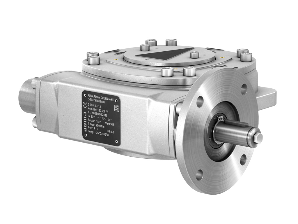
AUMA - Gearboxes GS
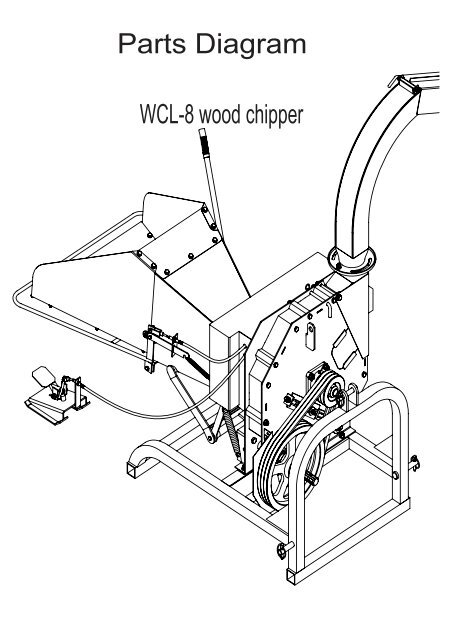
Parts Diagram - Chippers Direct

Assembly exercise: spur and worm gear (MT 123) – Material Testing Laboratory Equipment

NMRV Type System Drawing

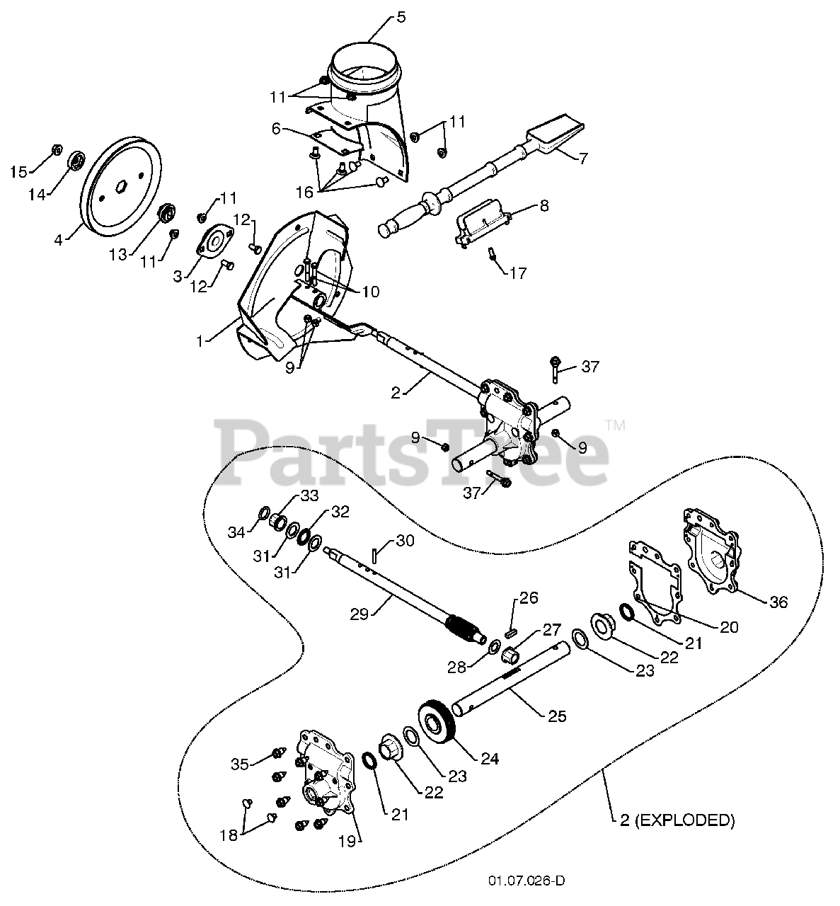
Murray 1696675-00 - C950-52592-1, Craftsman 21.0 Gross TP 30 Dual Stage Snow Thrower (2017) Parts Diagram for Gear Case Assembly (704027)
Poulan Pro 961940009-01 - Poulan Pro Snow Thrower (2010-06) Auger Housing / Impeller Assembly Parts Lookup with Diagrams

HydroWORKS 8607400 Aluminum Worm Gear Speed Reducer Instruction Manual

Gearbox Assembly - Worm Gear to Offset Shaft

1: Worm and sector steering gear system

DC GEAR MOTOR/DC MOTOR Doncen Motor
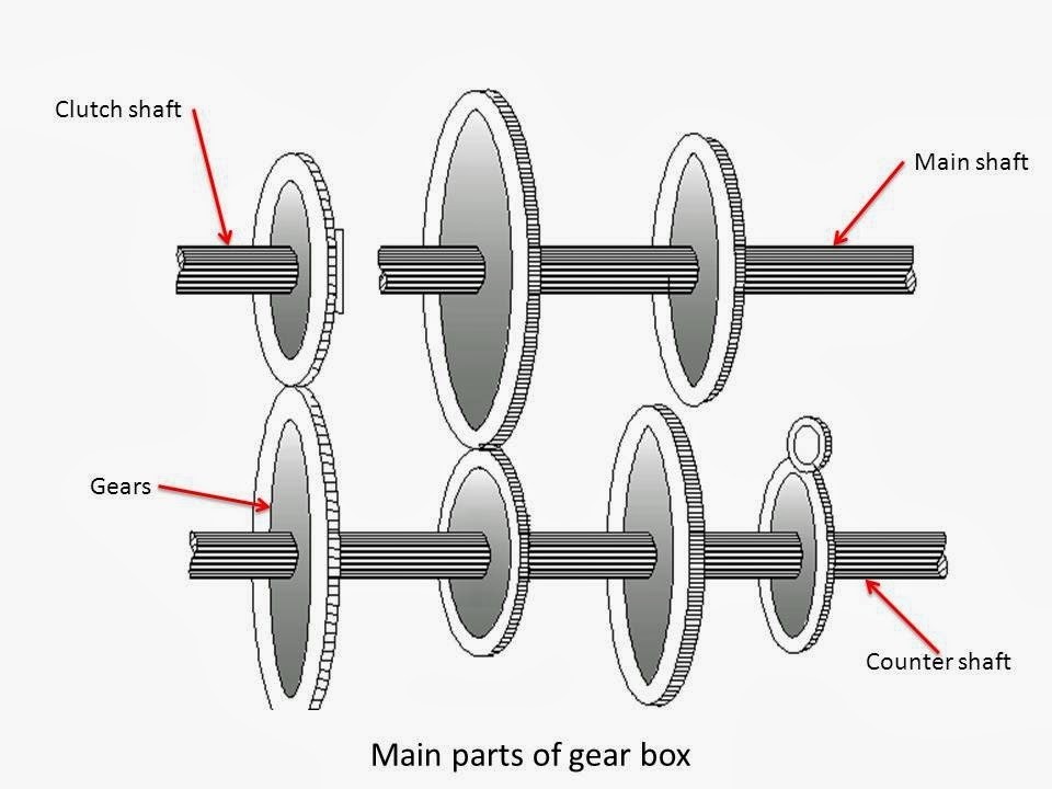
Gearbox Components and Parts: Everything You Need to Know - Industrial Manufacturing Blog

Image-assisted collision detection for calculation of an assembly interference matrix
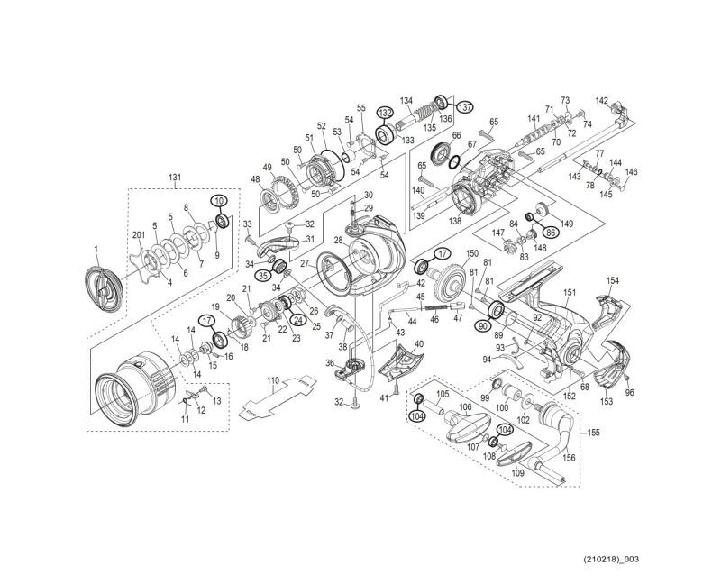
SHIMANO] Genuine Spare Parts for 21 EXSENCE 3000MHG Product Code: 043436 **Back-order (Shipping in 3-4 weeks after receiving order) - HEDGEHOG STUDIO
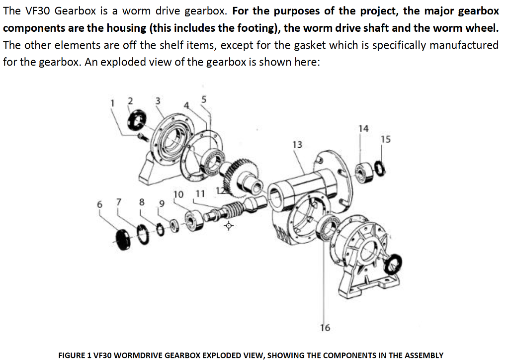
The VF30 Gearbox is a worm drive gearbox. For the

Parts List 38 260 12 95: Helical-Bevel Gear Unit KA77, KH77, KV77, KT77, KA77B, KH77B, KV77B, PDF, Gear
- HEDCON® Worm Drive & Reducer Gearbox
- Assembly & disassembly of worm gearbox # Gearbox repairing easy,आसानी से सीखें,கற்றுக்கொள்வது எளிதாக

- China EP-NRV Shaft Input Small Worm Gearbox / Worm Gear Speed Reducer , Manufacturer, Supplier, factory exporter distributor, made in China - EVER-POWER GROUP

- 5:1 Worm Gearbox NMRV30 Worm Gear Speed Reducer 9mm Input Shaft Diameter - NMRV30-G5-D9|STEPPERONLINE
- WORM Vertical Gear Box, For Industrial, Packaging Type: Standard at Rs 16000/piece in Kolkata