Wednesday, Jul 03 2024
Radius of curvature normal to the streamlines.

By A Mystery Man Writer

Design parameters of the two tested configurations.

r − x − θ) 3D coordinate system [6].

Full section spline thickness distribution.

Full section spline thickness distribution.

The S-shape section camber line.

r − x − θ) 3D coordinate system [6].

Second derivative over turbine blade surface.

3rd rotor hub section from EEE NASA report.
The Second derivative at the Leading edge.
Simple Torsion of a cube. The cube above covers the interval [−1, 1] ×

Total temperature ratio for Rotor35.

Second derivative B-spline with control points.
Related searches
- Glacially streamlined bedrock developed across an upland flanked by two

- A sketch of a streamline pattern. Solid lines are streamlines and the

- Sleek, streamlined orange car with smooth curves png download

- Kris Lin produces the stunning 'City of Light'—a majestic

- Streamline Moderne: The Whimsical Precursor to Mid Century Modern

Related searches
- Nike Dri-FIT Academy Men's Football Pants. Nike AU

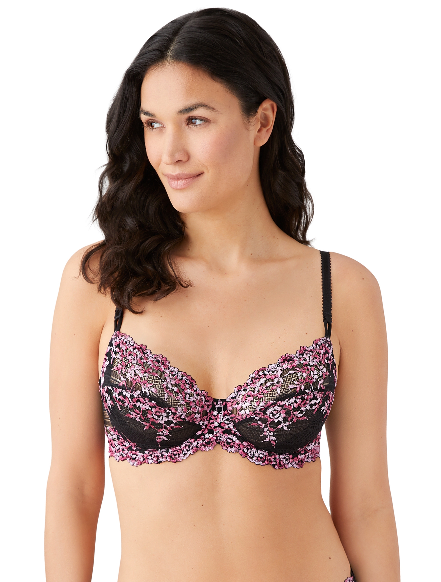
- Wacoal 65191 Embrace Lace Underwire Bra
- Nintendo shows off exercise-powered RPG for Switch, Ring Fit Adventure

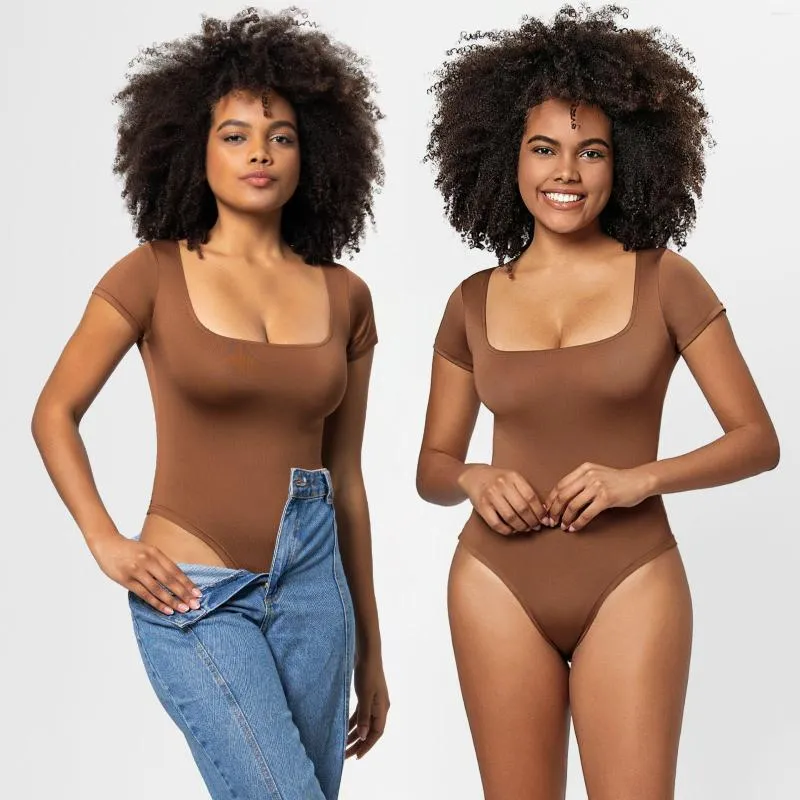
- Sexy One Piece Bodycon Bodysuit Thong Shapewear Bodysuit With Short Sleeves And Open Back For Women From Dwayverda, $11.89
- Buy COOFANDY Mens Big And Tall Hoodie Tracksuit Long Sleeve Casual Workout Sports Gym Jogging Sets, Light Grey, Medium at

©2016-2024, doctommy.com, Inc. or its affiliates